
This article covers the design and build process of the humidifier hardware for my Snake Tank Humidifier project.
- What + Why?
- How?
- Final Thoughts
What + Why?
The first and most important part of the Snake Tank Humidifier project is, of course, the humidifier system itself.
Goals/Requirements
The humidifier system will be responsible for delivering humid air to the snake tanks in some form. This includes a water reservoir and the system for delivering that water in an aerosolized form, including the container, tubing/hoses, mounting hardware, etc. The main requirements for this system are that:
- It needs to fit nicely in the available space on my current snake shelf setup. (Keep a look out for the post coming on that)
- It needs to hold enough water that it lasts for a while between refills.
- It needs to be easy to refill when the time comes.
- It needs to deliver the water in a sufficiently aerosolized format for maximum humidity increase. The finer the mist of water, the more it will humidify the air - larger drops will condense quickly and won’t provide much increase to humidity.
- It needs to be digitally controlled (almost anything can be digitally controlled as long as it’s powered by electricity)
How?
Possible Solutions/Exploration
There are couple options when it comes to creating humidity, the two I considered for this project are:
-
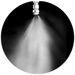
Pressurized misting system - This is a pretty straight-forward concept. You have a water pump (like this one) that pumps water through hoses (like these) and out of several very tiny holes (aka nozzles) which creates a bunch of tiny droplets in the air.
-
Ultrasonic transducer with airflow to the tanks - This option consists of an ultrasonic transducer that creates a fine fog-like mist when submerged in a body of water. That mist is then pumped through some kind of ducting system to the tanks.
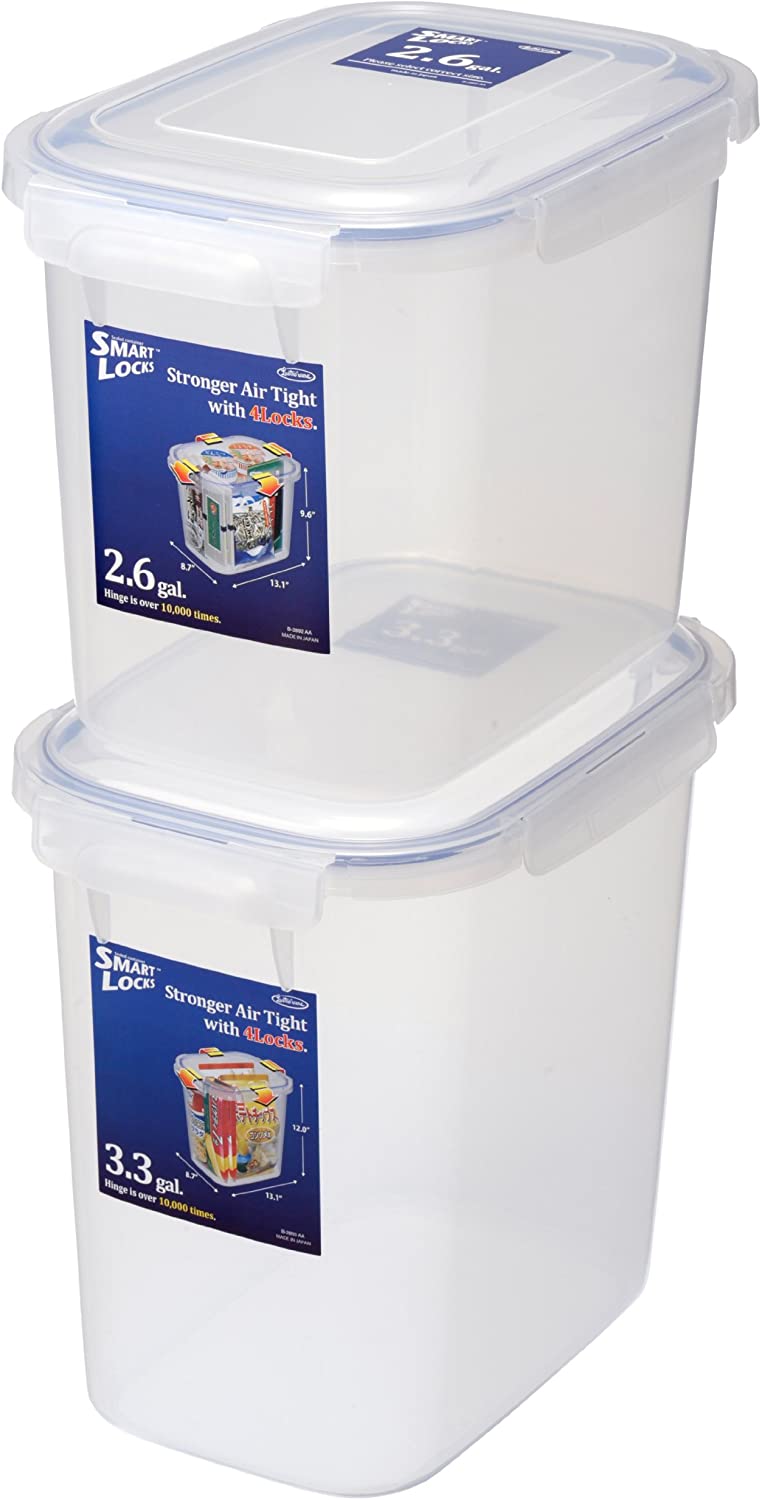 Both of these options require a water reservoir, I decided to use a basic plastic food container with a lid for mounting hardware to. I bought the 3.3gal size of this container from a local store in my area called the Container Store. The exact model I have isn’t available on amazon at the time of writing this, but a similar item that should still work with all of my designs can be found here.
Now, back to the misting system - the pressurized misting system at first seems like the best idea to go with, but on closer examination has a few drawbacks that I think can be addressed by using the other system. The first is the fact that I’m doing this as an electronics and design project to put my new 3D Printer to use, not as an exercise in learning about fluid dynamics. I don’t know enough about hydrodynamics/fluidics/whatever they call it to determine the correct water pressures to use, pumps to buy, nozzle sizes to use, and how all those variables effect each other. This video does a good job explaining the basics of misting systems and how water pressure effects the droplet size.
 Let’s explore the differences in high and low pressure misting systems. If I were to use low pressure (40-60 psi) provided by the tap, I would end up with large droplets of water, which causes several problems. For one, it will soak all the bedding in the tanks, which is not good for snakes, they need humid air, but dry ground. Another problem that comes with larger droplets is evaporative cooling. As all this water evaporates, it causes a phenomenon known as evaporative cooling (basically, as water evaporates it absorbs a large amount of heat energy from the surrounding air, cooling it in the process). I’m not sure exactly how pronounced this effect would actually be in practice, but ideally we would not be doing anything to remove heat from the tanks if possible, seeing as the snakes already require a large energy input to keep warm. Besides those issues, then there’s the problem of tapping into the main water system at my apartment for the initial pressure - just not feasible. If I were to go with a high pressure system it could be pumped from the reservoir and emit very fine droplets, eliminating the two previous issues, but would require expensive pumps and high pressure components throughout. I’m doing this project on a somewhat limited budget, and again, I’m not knowledged enough in designing fluid systems that I would trust myself to buy the right components the first time - not to mention the risk of a faulty seal spraying water all over the place. It’s not looking great for a pressurized misting system so far.
 Instead, let’s look at the ultrasonic transducer/atomizer option, and how it can help overcome these problems. An ultrasonic transducer/atomizer is a ceramic disk that utilizes the piezo-electric effect to flex and oscillate at extremely high speeds (100’s of thousand of Hz), turning the water into a fine mist that lingers in the air (this is how many household humidifiers work). Now, how can this address our problems? First, the problem of droplet size and all the surrounding issues that come with it. With the transducer, we are creating an ultra-fine mist (probably as fine or finer than a very tiny, and very expensive, high pressure nozzle system), and by pumping it to the tanks through directed airflow, we eliminate any water droplets and only supply humid air to the tanks. This eliminates condensation, wet bedding issues, and evaporative cooling effects inside the tank (all the evaporation happens inside the water reservoir, not inside the tanks). We also don’t have any expensive components needed for this, any high pressure connections to fail, or any flowing water that has a chance of leaking out. The worst risk of water leaking is from condensation within the ducting tubes dripping out, which I don’t see as a very significant issue.
Supplies
Now, with all that out of the planning out of the way, let’s talk about how to build this damn thing. Here is a list of components that we will need:
Parts:
- Water reservoir
- Ultrasonic atomizer
- Ducting tubes (1 1/2in sump pump hose)
- 40mm fans
- 3D printed mounting hardware (designs included below)
- 8-14 x M4 machine nuts and bolts
- 2 x DHT-22/DHT-11 humidity and temperature sensors
- 8 ft. 4 conductor shielded wire
Tools:
- JST connectors + crimpers
- Wire strippers
- Hot glue gun
- Drill and bit set with 5/8 in drill bit (I used a spade bit for this larger size)
- Screwdrivers
Atomizer
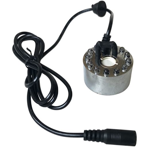
After getting a water reservoir, we need the atomizer component. It is a simple piece of hardware that will float inside the tank and create mist whenever supplied with DC 24V power. It conveniently comes with a power adapter and cord that plug in using a standard barrel jack. This is great because it means we can cut off the connector from the device wire, replace it with a JST connector that connects the device to the main circuit board, and integrate the original connector into our electronics case as our DC 24V power input, which will be used to control the fans as well.
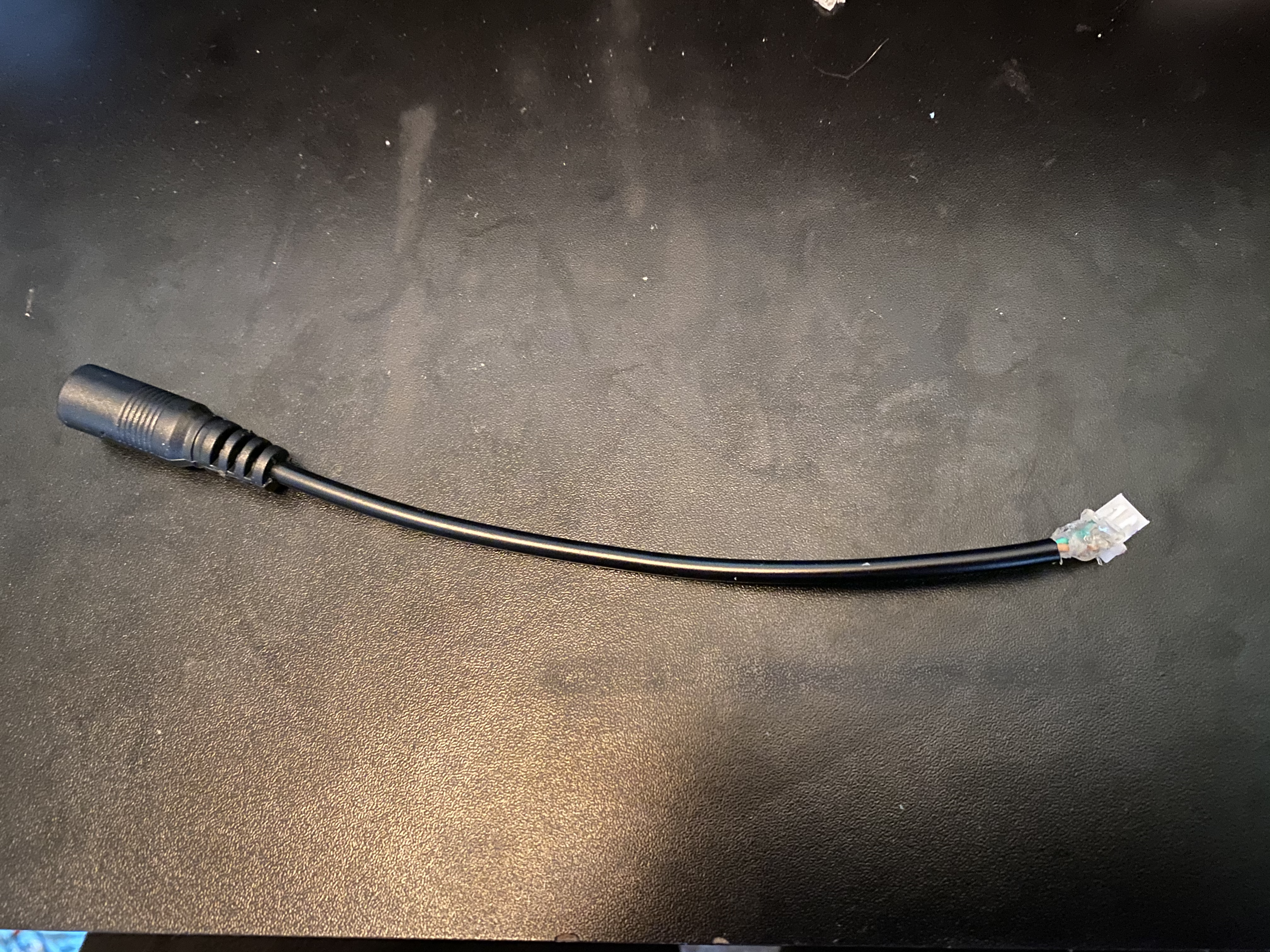
Cut female plug off device cord
I cut the female connector off the device, leaving about 6 inches of wire for connecting the plug to the main circuit board.
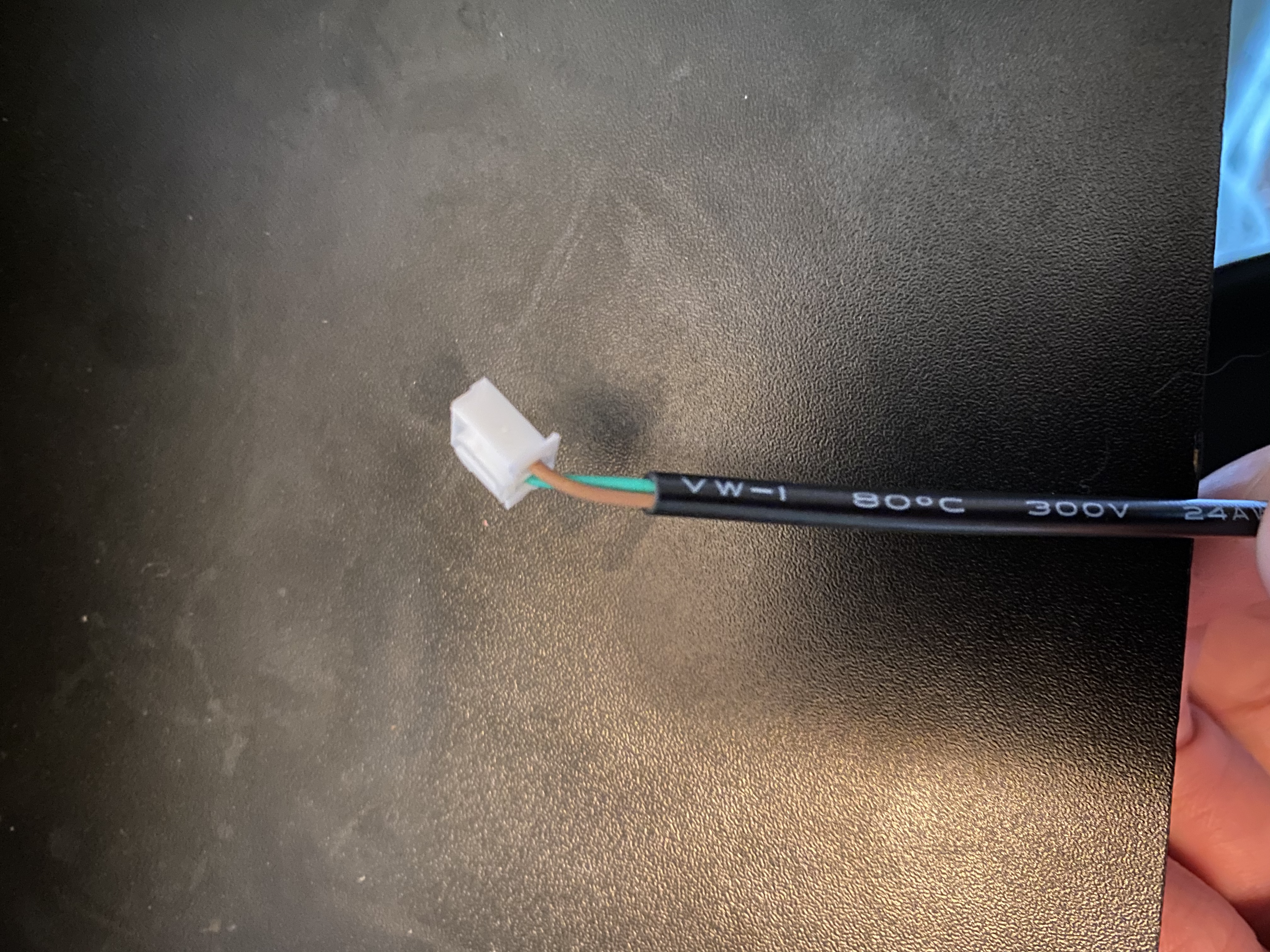
Attach JST connector to female plug
Strip the main insulation off the wire coming from the female plug by about 1/2-3/4 in. Then strip the two internal wires by about 1/4 in. Crimp one of the metal leads from the JST connectors kit to each wire, and then insert them into a male 2-pin connector end. This will plug into a female end on the main circuit board.
Attach JST connector to the devices wire
Follow the same steps in the above section to strip and add a male 2-pin JST connector to the cord on the device. This will be plugged into a port on the main circuit board that can be turned off and on by the arduino.
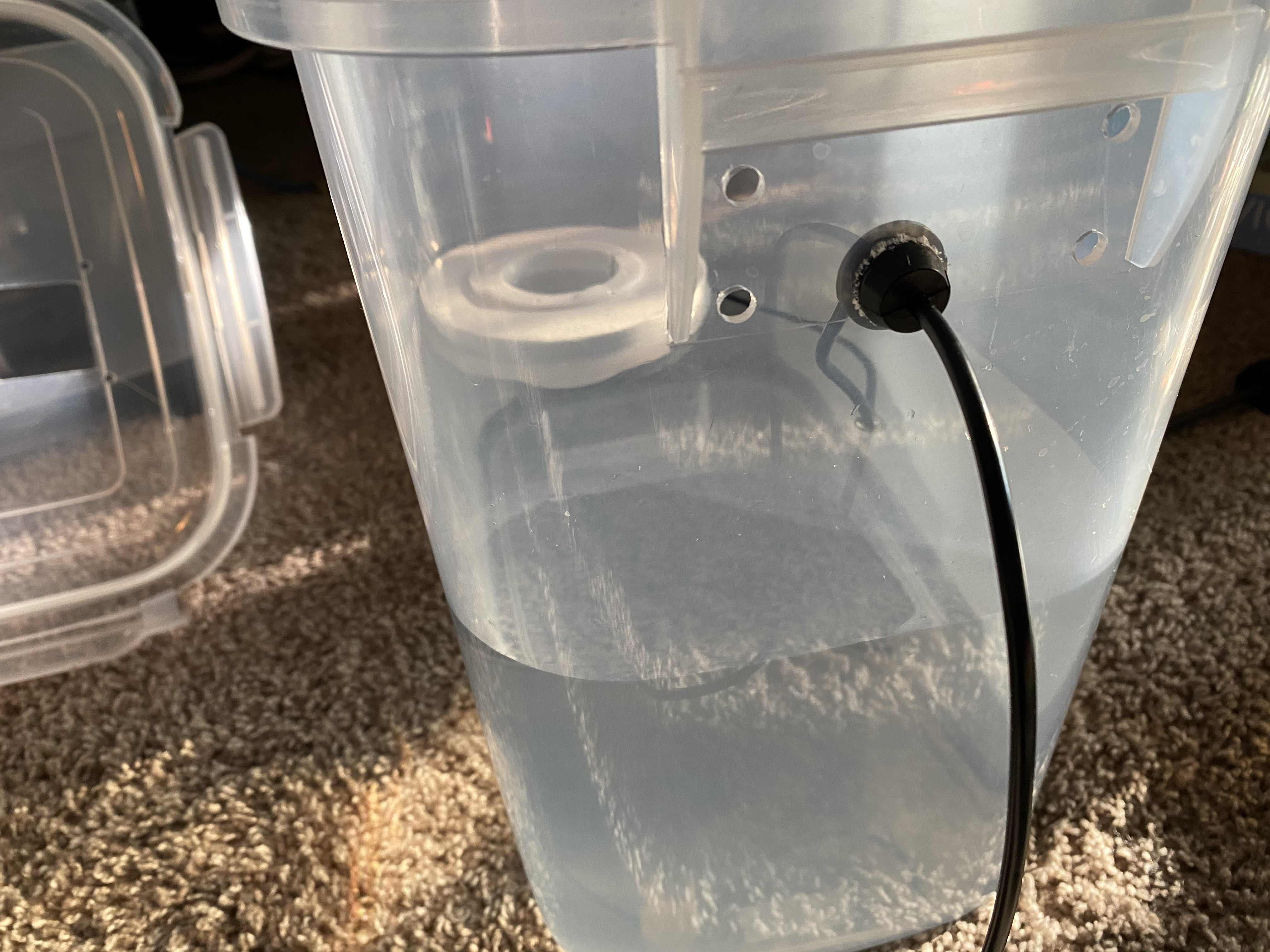
Run cord through side of reservoir
In order to get the cord for the atomizer out of the tank to plug into the main circuit board, we’ll need to drill a 5/8 in hole in the side of the reservoir to run the wire through. The atomizer includes a handy grommet that fits snugly on the wire to seal the hole, but I decided to drill this hole towards the top of the container to avoid any potential leakage issues. Finish this off with a layer of hot glue on both sides to hold everything securely.
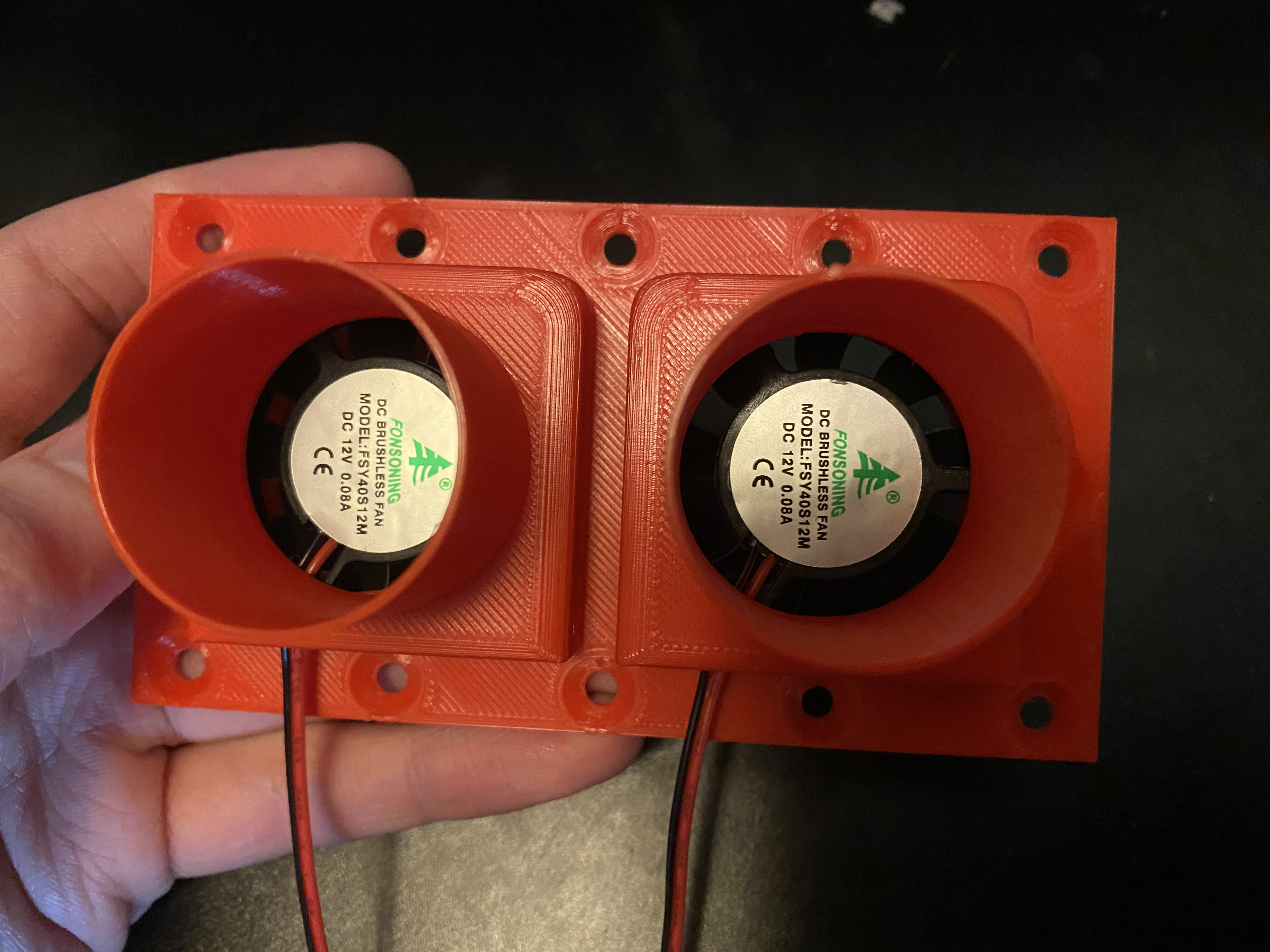
Fans, ducting, and mounting hardware.
To pump the humid air into the tanks, we will use two 40 mm fans, and 1 1/2in sump pump drin hose cut into smaller sections. Before we can attach these, we need to design and 3d-print some hardware to mount each end of the hoses to the humidifier box and the snake tanks respectively.
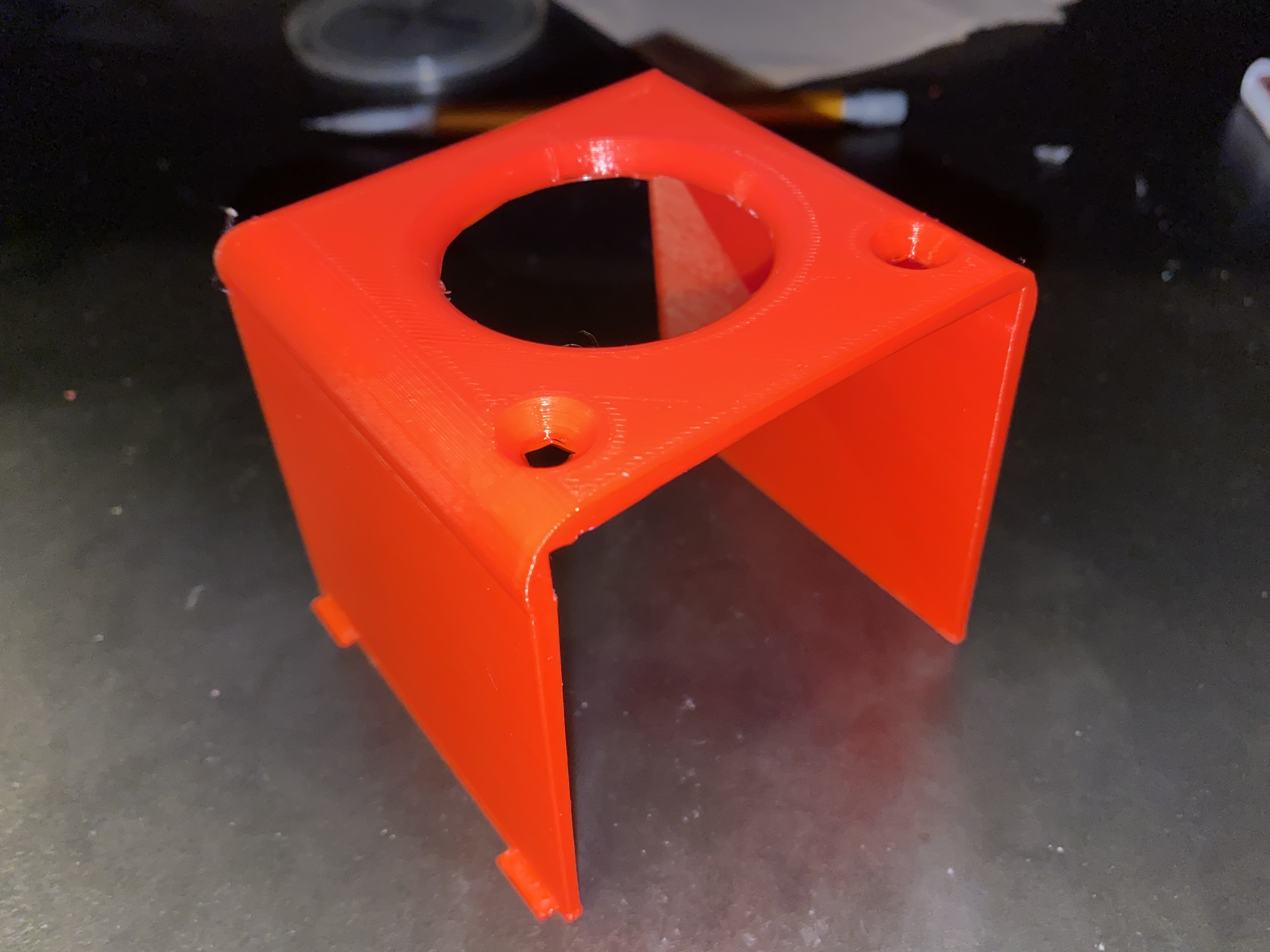
Fan and hose mount for reservoir side
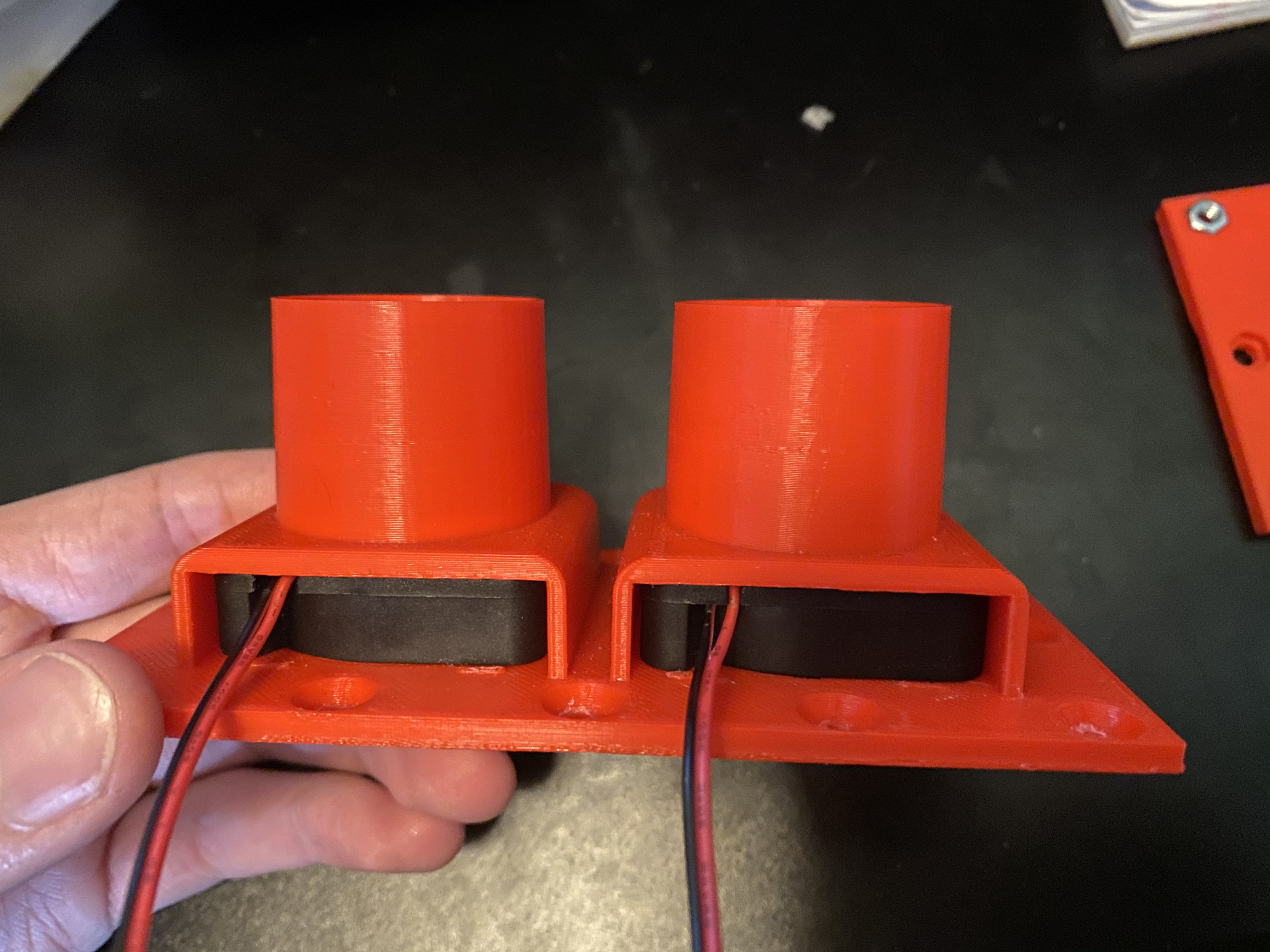
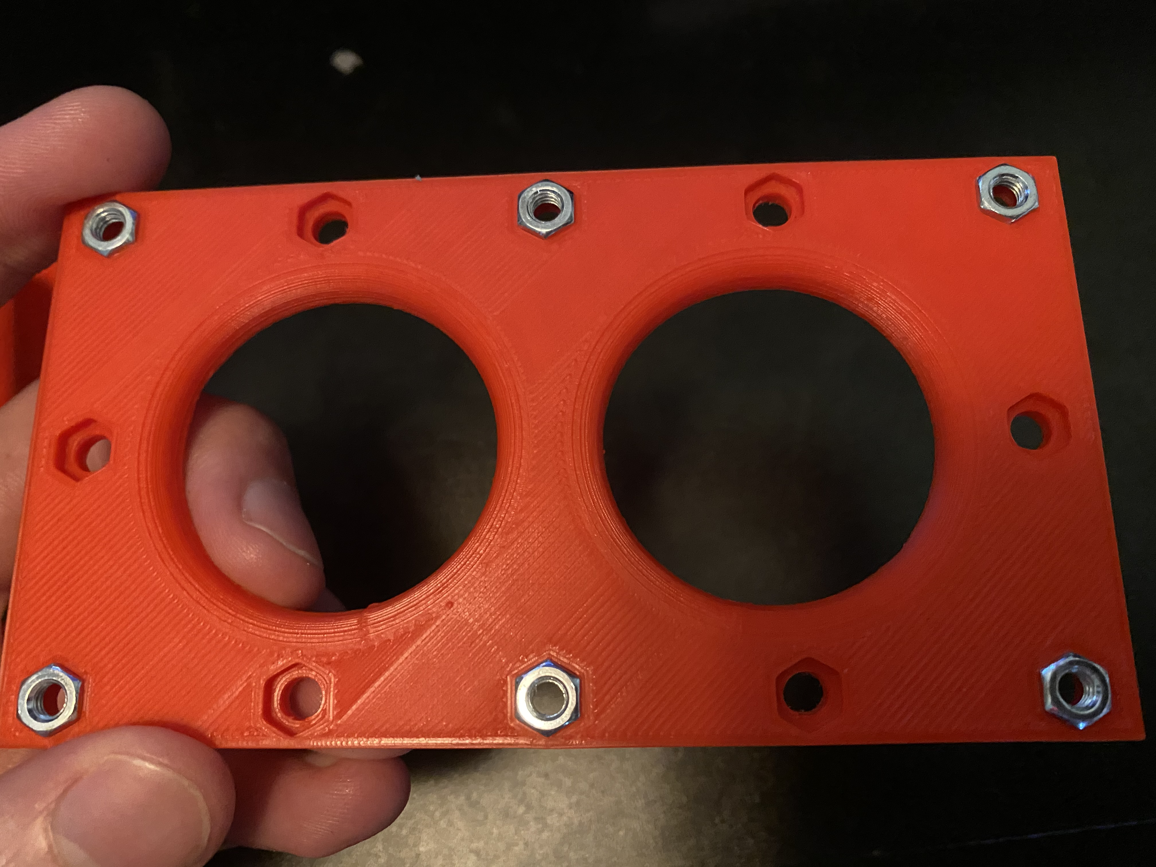
First, we’ll create the hardware for the reservoir side. Since we’re controlling two separate tanks, it will hold two fans, and have two hose mounting points, one for each tank. This hardware consists of a top piece with the fan housings and hose mounts, and a bottom plate used to secure the tank to the lid of the water reservoir.
Here is the design for the top part:
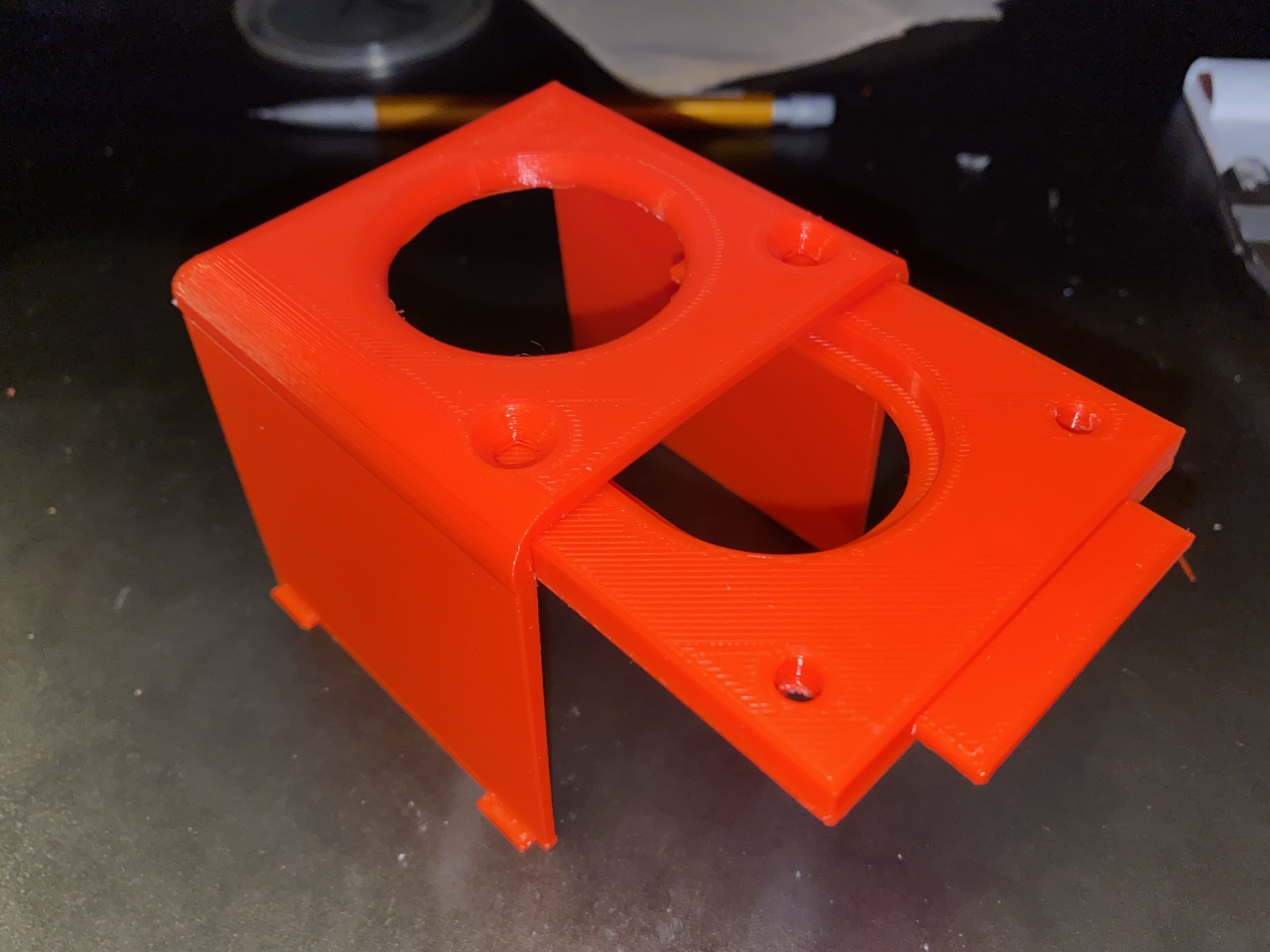
And the design for the bottom plate:
These two pieces will be secured with the M5 bolts and nuts. The bottom plate is designed to hold the nuts captive by lightly tapping them into place with a hammer. There are 12 nut/bolt holes in the design, but I found that 6 was plenty to hold everything securely (the 4 corner bolts, and the two bolts in the middle of the fan housings)
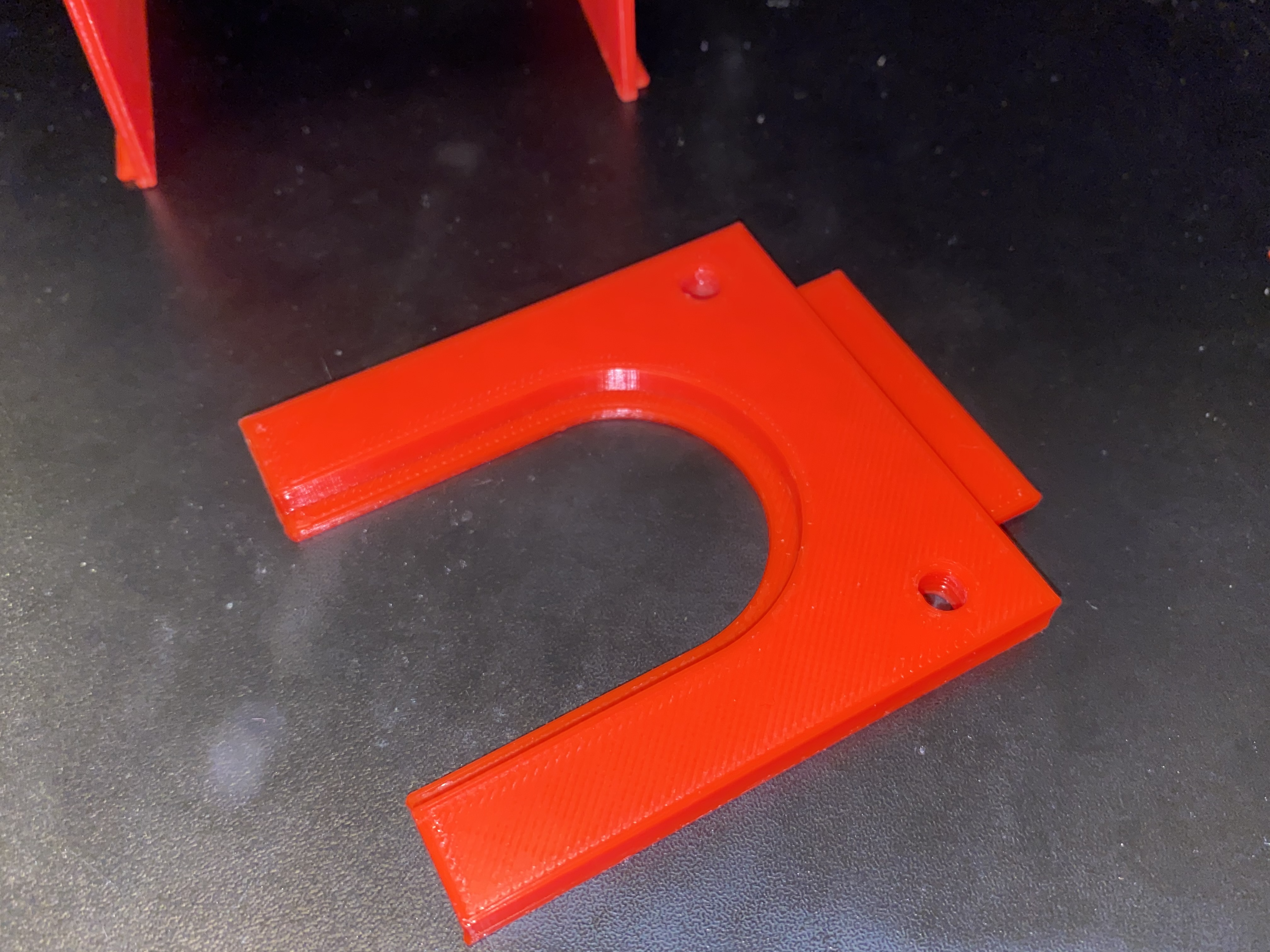
Hose mount for snake tank side
To mount the hoses to the snake tanks, I designed the below parts that are designed to snap into some geometry that’s included on each of the tanks, and clamp the hose in place by holding in between the ridges on the hose. Here is the 3D model of the full assembly:
There will be two sets of these parts, one for each tank. The two bottom legs clip onto the tanks and the hose is inserted into the top of the. Then the flat slider piece is inserted into the assembly, and is secured with two M4 nuts and bolts.
Here is what those parts look like once printed:
Humidity sensors
The final piece of the humidifier system are the two DHT-22/DHT-11 sensors that will allow us to read the humidity inside the tank. These will be super glued on the inside of the tank at the opposite end where the humidifier hose is attached, to give as accurate of a reading as possible. We will need to wire each sensor up using a length of 4 conductor shielded wire that is long enough to reach from the humidifiers location into one of the tanks. For me, this ended up being about 3 feet for one wire, and 5 feet for the other.
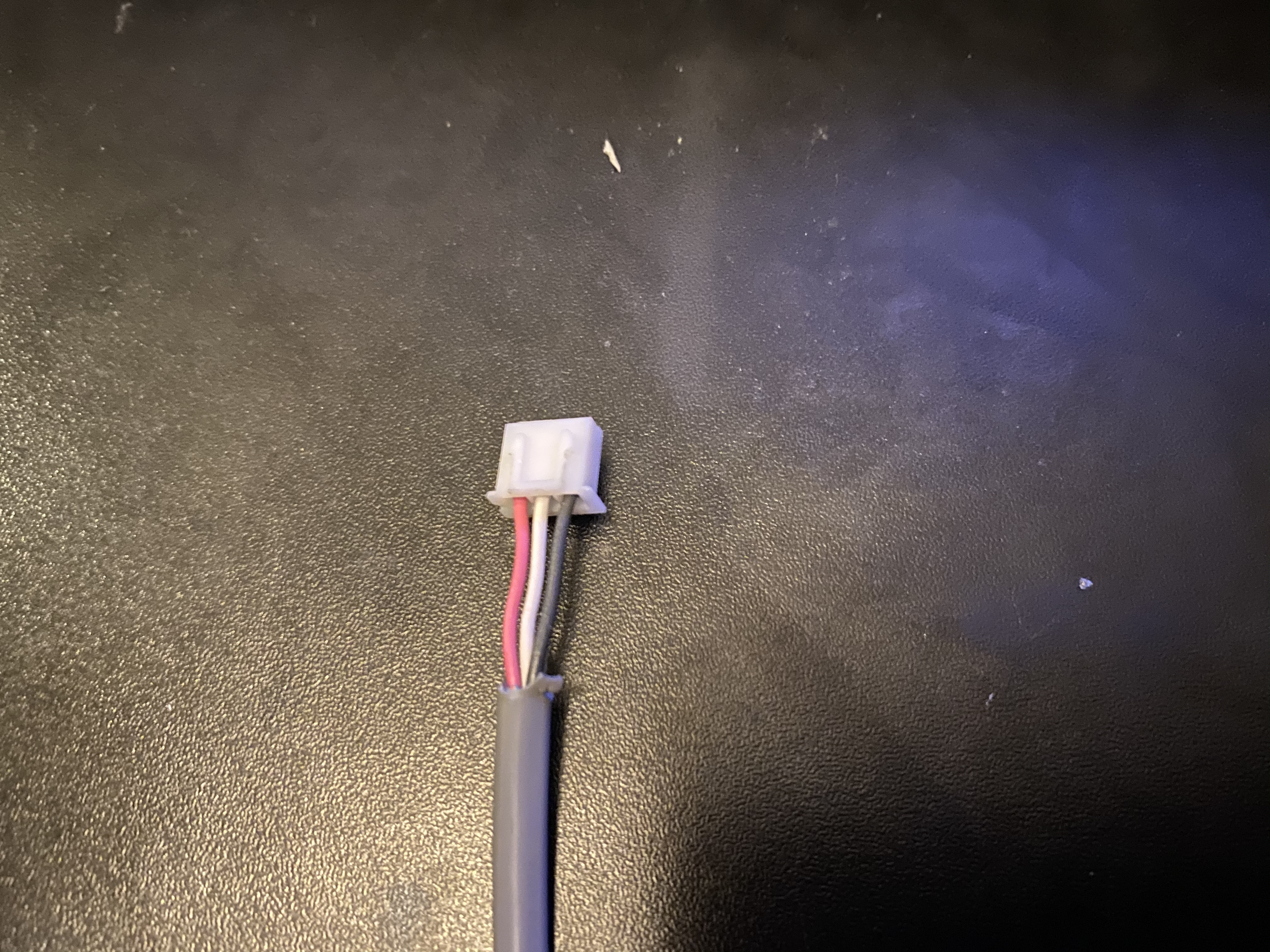
The red wire is connected to the positive terminal of the sensor, the black wire to the negative terminal, and the white wire to the output terminal.
Final Thoughts
This concludes the humidifier hardware portion of this project. In the next section I’ll go over the creation of the light controller hardware. Hopefully you found this informative or useful, let me know if the comments below, and be sure to check out some of my other articles.