
This article covers the design and construction of the automated Light control system for my Snake Tank Humidifier project.
What + Why?
The next main component subsystem for the Snake Tank Humidifier project is the lighting control box. This box will be responsible for switching on/off the different day/night lights for each tank.
Goals/Requirements
I wanted to design something that could improve on the current day/night timers that I am using, by having the ability to change the day/night automatically with the seasons, and even be able to replicate the lighting cycle of any place in the world, to better simulate the snakes’ native environment. To accomplish this goal for both snake tanks, I require the following:
- Two separate outlets connected to AC line voltage, one for day and one for night.
- Each outlet needs two plugs (one for each tank)
- Each outlet needs to be able to be independently switched off/on by an arduino microcontroller.
How?
On stock vs custom light control
I want to discuss a little more in depth my reasoning for building a custom switchable outlet box, rather than using one of the many existing out-of-the box day/night timer setups available online and in pet shops everywhere. The timer I currently use before designing this system works by having a dial similar to that on a wind-up kitchen timer, that completes one rotation every 24 hours. This dial has a bunch of tabs representing equal portions of that rotation that can be pulled out or pushed in to control whether the day or night light will be turned on during the period of time when the arrow is in that section. Each of these sections control 30 minute increments, the timers are pretty easy to install and configure, and they work pretty reliably in my experience.
So why would I go through the trouble of designing my own light controller? Well, for one, those timers are static and have to be changed manually to adjust for seasonal lighting differences, daylight savings time, etc. They are also basically a flip flop switch, meaning that at any given time, one light will be on and the other off; there is no point at which they can be both off or on simulataneously. With my system, I should have the ability to either blend the cycle switches together, or leave a period of no lighting in between the day/night switches.
However, my main purpose in building a custom system is to have dynamic control of the lighting schedule: To replicate the lighting in the snakes native territory, and to be able to alter the lighting schedule according to the season. This will have the added benefit of having timing controlled by syncing to an internet time server, rather than being a relative timer that stops and gets out of sync anytime it is unplugged or loses power for any reason.
Supplies
So the basic design is a custom outlet box with two separate outlets, each switched by it’s own 5V controlled relay. Below are a list of all the required tools and components:
Parts:
- 1 x 2 Gang outlet box
- 2 x duplex receptacle outlets
- 1 x matching outlet cover
- 2 x 5V relays with switching capacity >= 250V/10A AC current
- 1 x 3-prong AC power cord - you can buy something like this with pre-stripped ends, or use any random 3-prong power cord, like this or an old appliance power cable
- 16-18 AWG wire for line voltage (I harvested this off the end of my power cord, 1 1/2 feet or so should be plenty to wire up 2 outlets)
- 22 AWG wire for the 5V DC relay control lines
Tools:
- JST connectors + crimpers
- Wire strippers
- Hot glue gun
- Drill and bit set one with 1/4 in, and one with size matching your power cable diameter.
- Screwdrivers
- Multimeter/Continuity Tester
- Soldering Iron
Prepping the gang box
The first step is to gather components and prepare the gang box for wiring. We need one hole for the main power cable, and two more for each of the relays control wires
Power cable hole
Drill one hole in the side of the gang box with the same diameter as your chosen power cable, making sure the cable fits snugly, reaming the hole slightly larger with the same bit if needed.
Control wires hole
Drill two 1/4 in holes on the opposite side of the gang box for the relay control wires. Each relay will have three 22AWG wires for it’s control, so make sure that you can comfortably fit 3 wires through each of these holes without damaging them.
Wiring components
Once the gang box is prepared, it’s time to start wiring in all the components. This can be a kind of tricky process to get right, so I recommend checking out some video tutorials like this one for proper safety and techniques for wiring outlets.
Safety is the number one priority when dealing with electricity, especially AC line voltage, which has the power to KILL YOU if you aren’t careful. Please take this seriously and make sure everything is unplugged before working on any wiring.
Here is the wiring diagram that will be referred to throughout the rest of the wiring section:
Harvest wire from power cord (optional)
If you decide to harvest the outlet wiring from an old power cord like I did, cut off a length of about 1-1 1/2 ft. of wire from the end of the cable and remove all of the outer insulation so you’re left with three individual strands of wire. If you’re using separate wire for inside the gang box, skip this step.
AC wiring to relays
First, we’ll wire up the power cord to the outlets, using the relays to break the “hot” wire to the outlets. As a safety rule for AC and other high voltage circuits, you should always switch the “hot” wire (for more info on why, check out this article from allaboutcircuits.com). Each outlet will have a common ground and neutral connection, and separate hot connections switched by each relay. We’ll use the normally open ports of the relay to ensure that we have to actively turn on the outlets, rather than having them be on by default.
After inserting the power cord into the previously drilled hole, tie the ground terminals of each outlet together with a 4-5 in. length of green wire, and then connect the ground wire of the power cord to one of these terminals. Next, connect the neutral terminals of each outlet with a 4-5 in. length of white wire, and then connect the the neutral wire of the power cord to one of these terminals.
Next we have to wire up the relays in series with the hot wire to each outlet. Start by soldering two 4-5 in. lengths of black wire to the hot wire of the power cord, and securing one of them into the “COM” (common) terminal of each relay. Then use two more varying lengths of the black wire to connect the “NO” (normally open) terminal of each relay to a different outlet. This concludes the wiring for the AC portion of the light controller.
Relay control wires
Next we need to connect some wires to the DC control terminals of each relay that route outside the box to connect to the arduino. I try to follow a somewhat standard coloring system for my DC circuits, in this case it’s red for DC+, black for DC-, and yellow for control/signal voltages. Simply cut 2 lengths of each color, connect them to the respective terminals on the relays: red for the “DC+”, black for the “DC-“, and yellow for the “IN” terminal. Feed the 3 wires from each relay out a separate one of the 1/4 in. holes drilled previously.
We’ll need to use another length of the 4 conductor cable and a 4-pin JST connector to create a wire that plugs into our main circuit board. One end of the cable will connect to the relay wires coming from the box, and the other end will have a 4-pin JST connector attached to it.
The red cable strand is connected to both of the positive (red) relay control wires, the black strand to both negative (black) control wires, and the green and white strands each connected to a separate input (yellow) relay control wire.
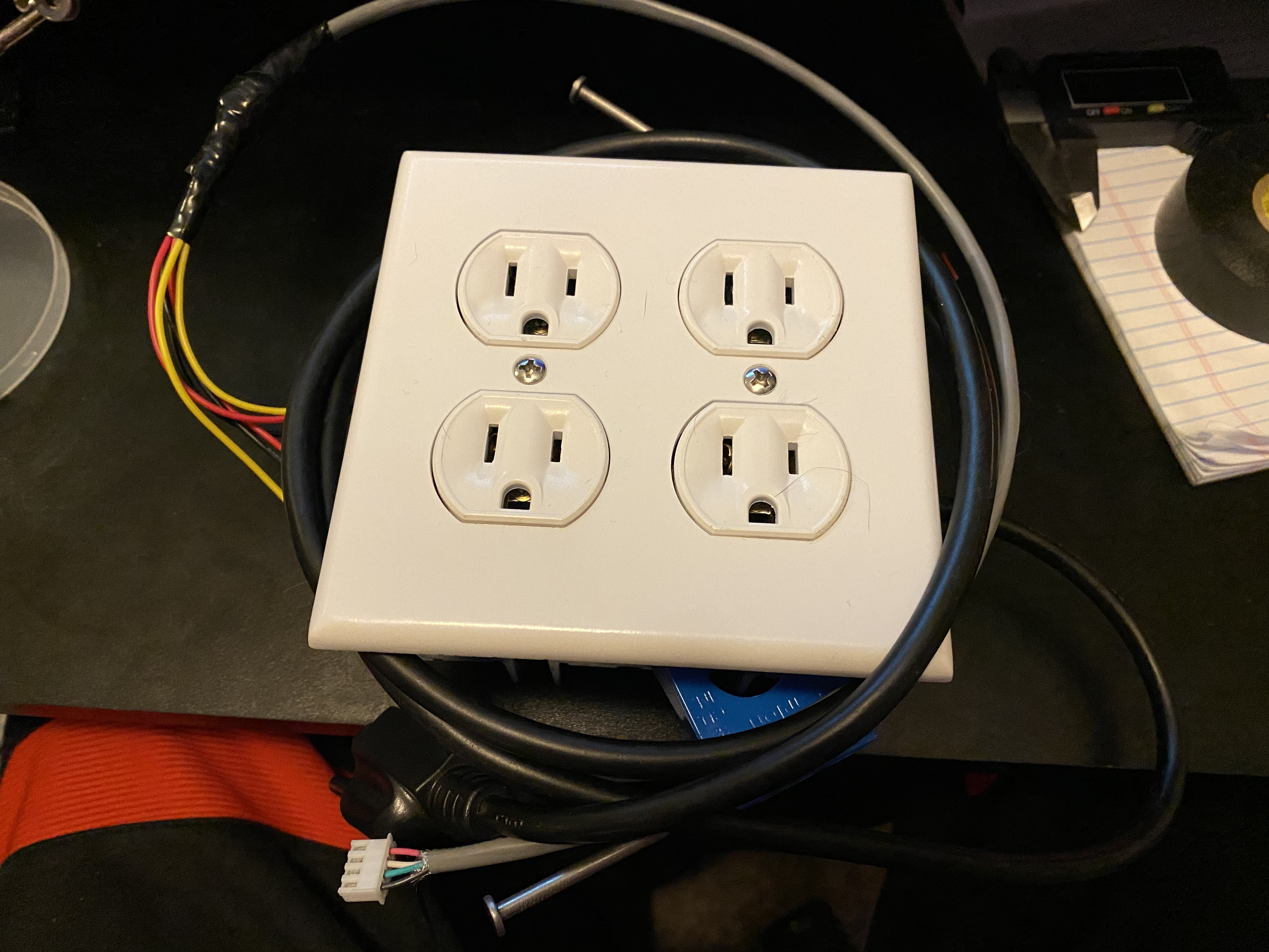
Finish assembly
Now that all the internal wiring for the light controller is completed, it’s time to put everything together and test. Start by securing the relays to the side of the gang box using some hot glue. Be sure to test the fit of the relay with both outlets in position before using glue, to avoid any fitment issues with them. Once the glue dries, make sure any loose wiring is stuffed down in the box out of the way, and screw each of the outlets into the screw holes on the gang box. Finally, screw the outlet cover in place to complete the assembly of the outlet box.
Testing
To test the lights, I connected an arduino nano into a breadbord, and connected the + and - wires to the 5V and GND terminals on the arduino respectively, and plugged a lamp into one of the outlets. Touch the control wire for that outlet to the 5V terminal and ensure that the lamp turns on. Repeat the same with the other outlet, touching it’s control wire to see if it turns on the lamp.
Points of failure:
- Relay - If the relays are working properly, you should be able to hear an audible click sound from them when the are activated or deactivated. If you don’t hear this, check the connections to the DC terminals of the relay.
- AC wiring - If the relays are working, but the lamp doesn’t turn on, there is a problem with the wiring of the outlets or the AC portion of the relay. Check that each terminal has a good connection, and review the wiring diagram to make sure that everything is properly wired.
Final thoughts
That’s it for the light controller. In the next section of this project, we’ll cover the design and construction of the main circuit board for the humidity controller system. Hopefully you found this informative or useful, let me know if the comments below, and be sure to check out some of my other articles.