This article covers the design and construction of the main control circuitry and it’s 3D printed housing for my Snake Tank Humidifier project.
What + Why?
The next main component subsystem for the Snake Tank Humidifier project is the control circuitry. This will be a circuit with an onboard Arduino NANO 33 IoT, and female JST connections for all the individual components that need to be controlled.
Goals/Requirements
The control circuitry has several components that need to be controlled, and that operate at two main voltage levels. I’ll outline each of the sub-components below, along with their requirements:
- Temperature/Humidity Sensors - There are two DHT-22 temperature/humidity sensors that will need to be powered and read from.
- Operating Voltage: 3.3V DC
- Control Pin(s): D2, D4
- Pin mode: INPUT
- Connection mode:: 2 x three-pin JST connectors
- Ultrasonic Atomizer Unit - The atomizer unit needs to be turned off and on depending on the humidity levels in the tanks.
- Operating Voltage: 24V DC
- Current Draw: 700mA
- Control Pin(s): - D6
- Pin mode: - OUTPUT
- Connection mode:: 1 x two-pin JST connector
- 2x 40mm Fans - There are two fan that provide airflow from the water reservoir to the tanks. These need to be controlled independently from the fans()
- Operating Voltage: - 12V DC
- Current Draw: 80mA each, 130mA in series
- Control Pin(s): - D8
- Pin mode: - OUTPUT
- Connection mode:: 2 x two-pin JST connectors
- Light Controller - The light controller has two control wires, one for day control and one for night control.
- Operating Voltage: - 3.3V DC
- Control Pin(s): - D10, D12
- Pin mode: - OUTPUT
- Connection mode:: 1 x four-pin JST connector
Power supply
- The arduino will be powered via it’s micro USB port connected to a wall charging brick, while the fans and the atomizer will both be run off the $24V$ DC wall power supply included with the atomizer.
Choice of Arduino
A bit more about the Arduino I’m using: I chose this specific microcontroller for several reasons, primarily the included WiFi and BT connectivity capabilities (via an onboard NINA-W102 module), as my eventual goal is to design a mobile app that can connect to and control the humidifier system. This specific model also has better performance than the Arduino Uno, due to it’s architecture (32 bit ARM CPU vs Uno’s 8-bit ATmega CPU), vastly improved flash (256KB vs Uno’s 32 KB) and SRAM memory (32KB vs Uno’s 2 KB), increased pin count (14 digital I/O pins vs Uno’s 6 digital I/O pins), and USB-micro connection, and a much smaller size.
How?
Powering Fans and Atomizer
The power supply we are using provides $24 V$ DC with a max current of $1000 mA$ ($1A$). Since the atomizer runs off of $24 V$ and draws $700 mA$, it can be powered directly from the power supply, and we leave $1000 - 700 = 300 mA$ to work with before overloading the supply.
The fans on the other hand, require $12 V$, which means we need to step that voltage down to avoid overpowering the fans. Luckily, since the fans should both have the same impedance, they will split the available voltage evenly among them when connected in parallel.
According to the manufacturer, the fans should draw a max of $80 mA$ - two fans in series should draw $80 * 2 = 160 mA$. However, I plugged the fans in and measured the current with a multimeter and they only draw about 130mA, which puts us at $300 - 130 = 170 mA$ under our max current rating. I’ll add another small resistor (~$10 \Omega$) in series with the fans, just to run them slightly under voltage as well, which should help with longevity.
There’s one last detail to attend to before we move on to switching these components though, and that is a little issue called back-EMF. Back-EMF is a common issue when driving inductive loads (like the DC motors inside our fans). Lenz’s Law tell’s us that a change in current through an inductive load or the movement of a magnetic field through a conductor induces a voltage in opposition to that motion. Electric motors work by using current to induce an electromagnetic field inside the motor to create rotational motion from stationary magnets (technically, it depends on the design of the motor, but the back EMF is produced regardless of whether the magnet or the conductor rotate, since they have the same relative motion either way). When the current flow through the motor stops, the magnets inside continue spinning, and induce a voltage potential in opposition to the polarity of the original applied voltage until the motors come to a stop. This means you will have current flowing backwards through your circuit, and if not properly accounted for, it can wreak havoc with the sensitive components on the arduino board.
Our atomizer has it’s own internal circuit board that should (hopefully) account for this issue, (if it even exists there in the first place) - from the little research I’ve done on piezo-disks, they should not generate any substantial back-EMF unless external pressure is applied to them. Therefore, I can (hopefully) safely ignore the issue of back EMF from the atomizer module.
Our fans, on the other hand, are an inductive load at a decent voltage ($12 V$ each) with absolutely no control circuitry, and are prime suspects for back-EMF issues. Not to worry though, the solution is very simple: Add a flyback diode across the motors that will allow for the generated current to flow through it instead of back through the rest of the circuit board where it could potentially damage components. A diode is essentially a one-way valve for electricity - it allows current flow in one direction and opposes current flow in the other. At normal operating voltage, the potential across the diode will have a polarity such that it does not allow any current to flow through it, and will not interfere in the circuits operation. However, once the normal operating voltage is removed, the back-EMF induced by the motor will produce a voltage with the opposite polarity that, due to the diodes orientation, will be allowed to flow through the diode and back to the source/ground potential of the induced voltage (AKA the motor). This is a fairly dense explanation with a lot of jargon, so if it doesn’t make much sense now, it should hopefully make more sense once we start applying these concepts to the circuit design.
Switching Fans and Atomizer
To control the fans and atomizer, we need a way to switch the 24V DC voltage from the power supply only using the $3.3V$ output pins of our Arduino. This “digital switch” is called a transistor, and it’s at the heart of nearly every piece of electronics we use today. There are many different kinds of transistors, with different applications for each. I originally intended on using a MOSFET (Metal Oxide Semiconductor Field-Effect Transistor), a type of transistor for higher power applications that is regulated by a gate voltage. However, after a trip to my local electronics supply store to purchase components, I ended up leaving with a pack of TIP31A BJT (Bipolar Junction Transistor) power transistors in a TO-220 package. I chose these since they were much cheaper than MOSFETs and still fit within the required power ratings for my application. The main difference between a BJT and a similarly spec’d MOSFET, is that a BJT is regulated by current flow, rather than voltage.
Connection points
The first step in designing the circuit is to determine what external components will need to be connected to the board.
The sensors and light controllers are all easy to design for, since they just hook directly up to the Arduino’s power and ground pins and digital I/O pins:
- Light controller
- The light controller has one 4 pin connector
- DC+ (arduino 3.3V)
- DC- (arduino GND)
- Cd (day control, arduino D10)
- Cn (night control, arduino D12)
- Sensors x 2
- Each humidity sensor will each have a 3 pin connector
- DC+ (arduino 3.3V)
- DC- (arduino GND)
- C (control pin, arduino D2 and D4)
Since the atomizer and fans are switched by transistors on the board, there will only be 2 pins connecting them to the board:
- Atomizer
- The atomizer has one 2-pin connector
- DC+
- DC-
- Fans
- The two fans each have one 2-pin connector
- DC+
- DC-
Finally, we need one more 2 pin connector to provide the 24V DC input
- DC 24V in
- This input will power the atomizer and fans, and be switched by the MOSFETs
- DC+
- DC-
Circuit Design
So now that we have all our external connections accounted for, it’s time to design the logical schematic for the circuit. To do this, I’ll use a free but extremely powerful EDA software called KiCad (pronounced key-cad). KiCad will allow us to design a logical circuit schematic, then design a PCB from that schematic, view a 3D rendering of the PCB, and finally generate the design files that we need to order our custom PCB from a vendor. Before designing the circuit, we’ll need to import any missing component symbols and footprints into our library. For this circuit, the only thing I had to manually import was the transistor:
- TIP31A power transistor
- The included component libraries include many different kinds of transistors, many also in the TO-220 package as well. However, none of them have the same specs as the TIP31A, and as a general practice I like to keep things as accurate as possible from the beginning, so that I know exactly what I’m looking at if I need to come back and make changes in the future. I found symbols, footprints, and 3D models for the TIP31 component here, and installed them using these instructions. I’m not going to go through this process here, but leave a comment below if you’re interested to hear more or have questions about the process.
I’m going to gloss over the details of the KiCad design process and focus on the end result - that could be an entire article in it’s own right, and this one already feels a little bit too long to begin with! If you’d like to learn more about designing circuits, check out these great videos that I used as a guide (Schematic Capture with eeschema and PCB Design with pcbnew) Based on all the requirements and details I’ve outlined thus far, I came up with the following schematic design in KiCad:
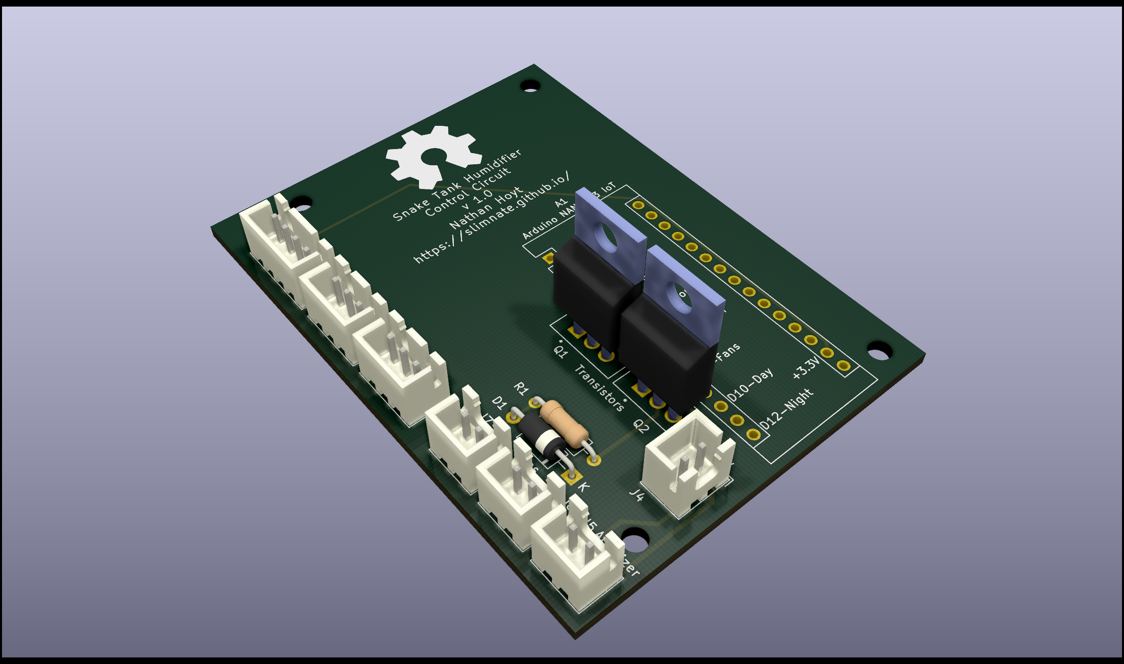
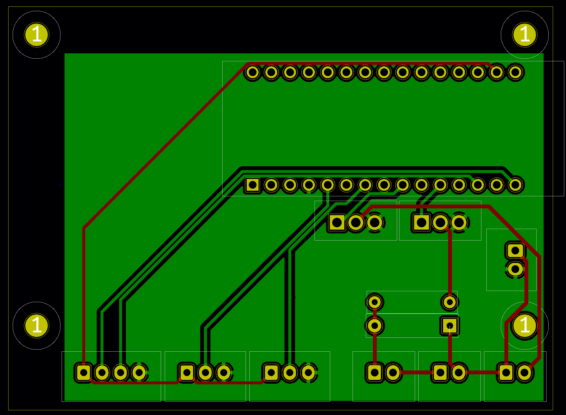
From that schematic, I then created the following PCB design (red is the front layer, green is the back layer):
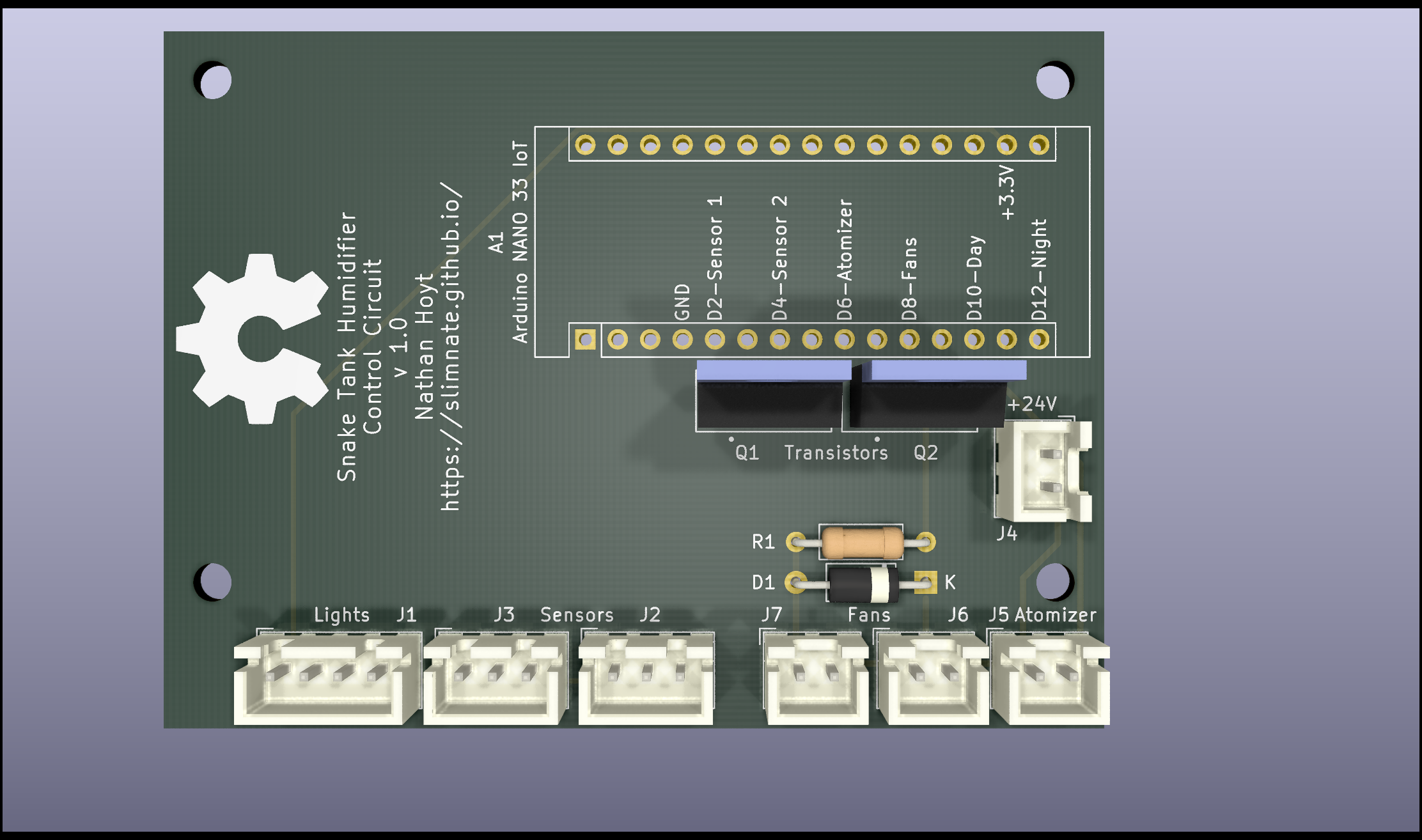
This completed design renders to the following:
Before we can finally get on to assembling the circuit, we have to order the PCB’s from a manufacturer. I used JLCPCB to order 5 copies of the circuit board (the minimum order amount) for $2 plus shipping; about $13 in total. The process was pretty simple, they have instructions on their site that walk you through exporting the necessary files. One you submit them, it generally takes 2-3 days for production, and about a week for shipping.
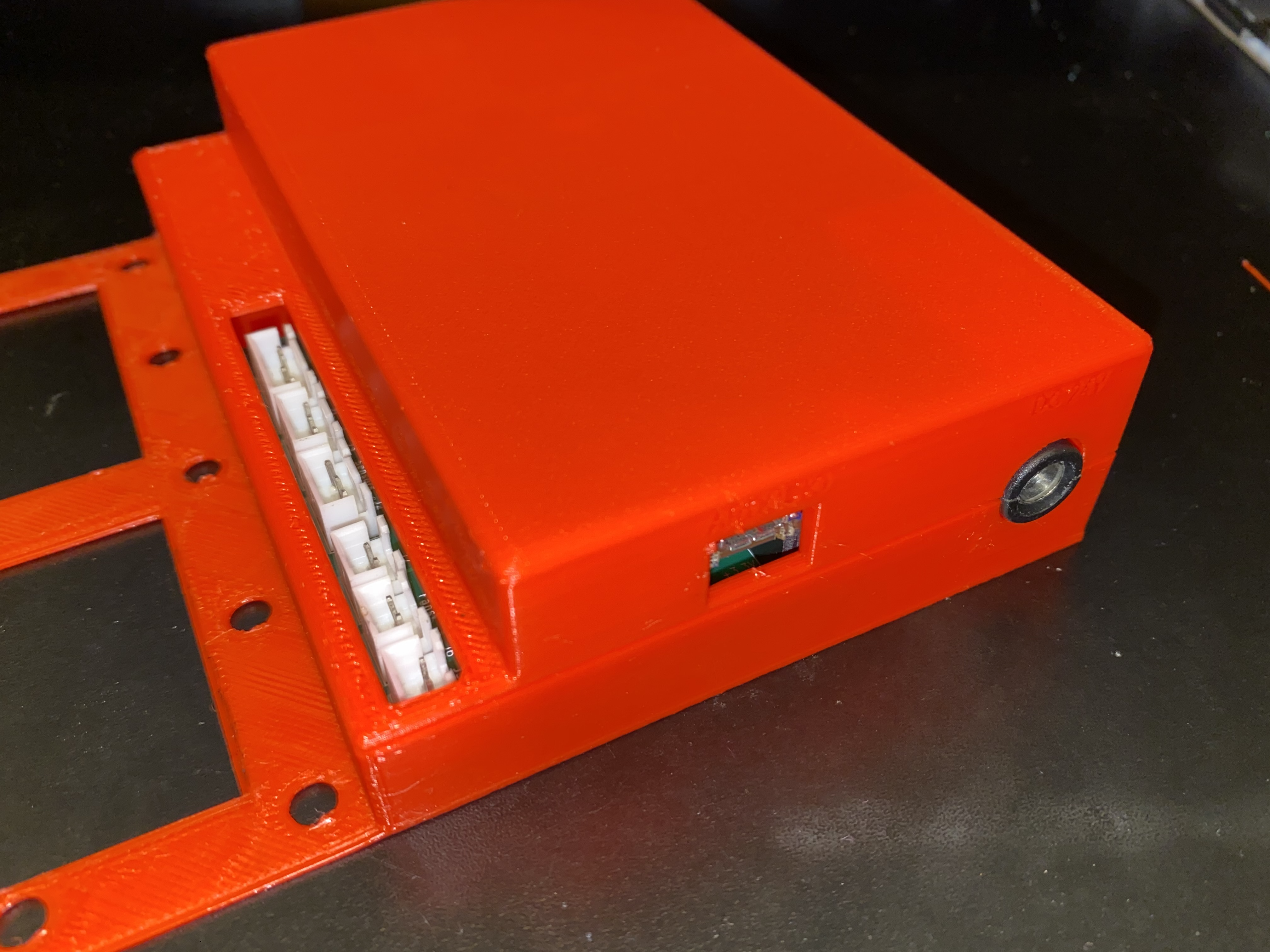
Electronics housing
While waiting on the PCBs to arrive, I got started on the initial design for the 3D printed electronics housing. This will need to have mounting posts that hold the circuit board in place, a place to mount a barrel jack inside the housing for the 24V DC input, and openings for the various JST connectors that plug into the circuit board.
I started by designing this 2-part barrel jack housing that will integrate into the top and bottom of the case to securely hold the barrel jack in place when snapped together:
From there, I got started on the housing model by exporting a 3D model of the circuit board from kicad, and importing it into Fusion 360, my 3D modeling software. Using the circuit board model and the barrel jack holder I previously designed, I came up with the following design for the electronics case that integrates with the fan mounting hardware to secure it to the rest of the system:
Components list
Parts:
- 1 x Custom Printed Circuit Board - Ordered from JLCPCB
- 2 x TIP31A Power Transistors - any power transistor will work as long as they are spec’d to at least:
- Max voltage from collector to emitter: $V_{ce} >= 24V$
- Max current from collector to emitter: $I_{ce} >= 700mA$
- Saturation voltage from base to emitter: $V_{be} <= 3.3V$
- Datasheet for TIP31A
- 1 x $10 \Omega$ resistor
- 1 x 1N4001 Diode - Any diode with the following ratings or better should work:
- Max DC forward voltage: $V_{dc} >= 24V$
- Max average forward current: $V_{fc(av)} >= 150mA$
- Datasheet for 1N4001
- 1 x Arduino NANO 33 IoT
- 4 x M5 machine nuts and bolts
- 1 x 3D printed electronics case (files included)
Tools:
- JST connectors + crimpers
- Wire strippers
- Drill and bit set one with 1/4 in, and one with size matching your power cable diameter.
- Multimeter/Continuity Tester
- Soldering Iron
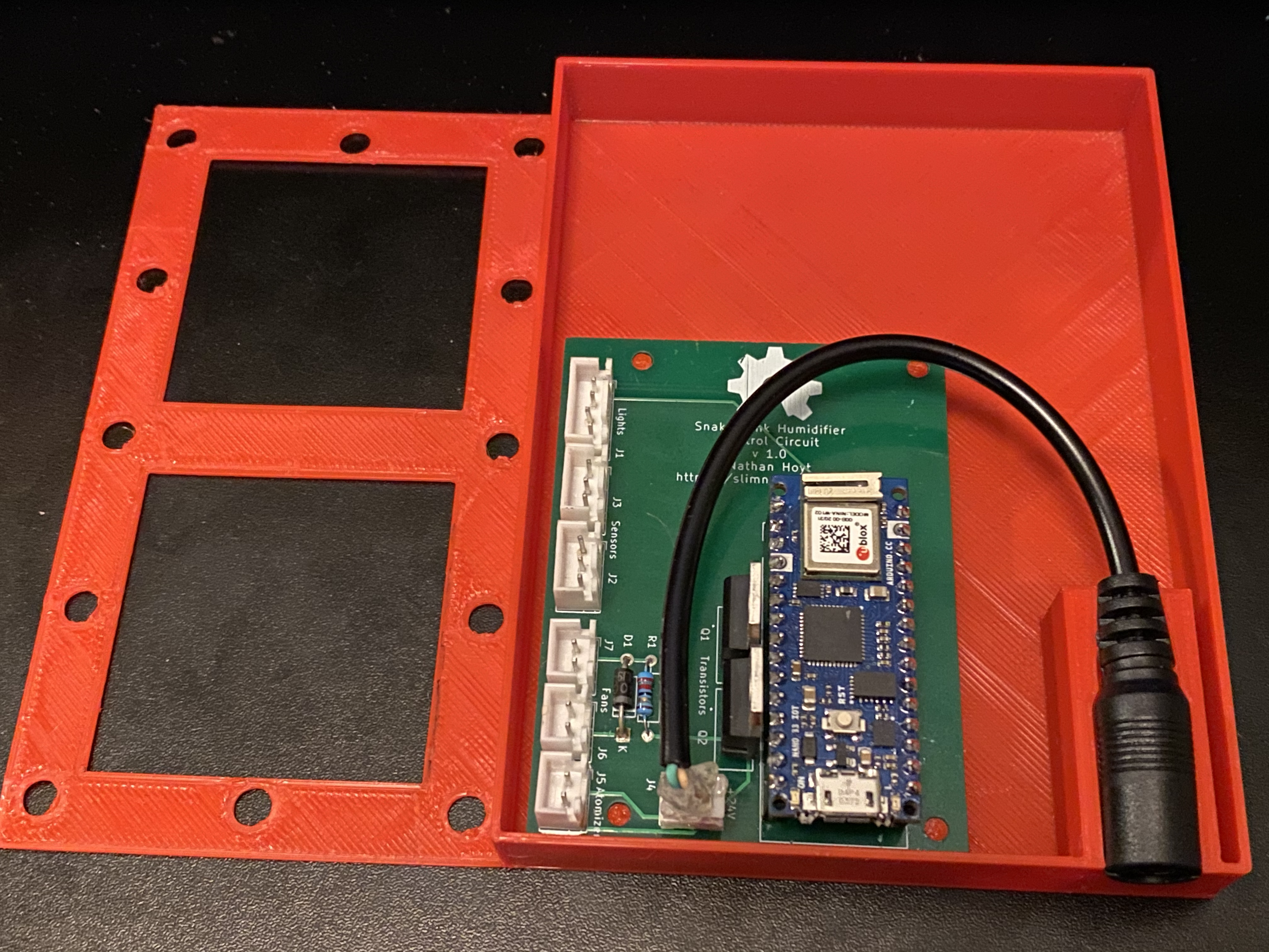
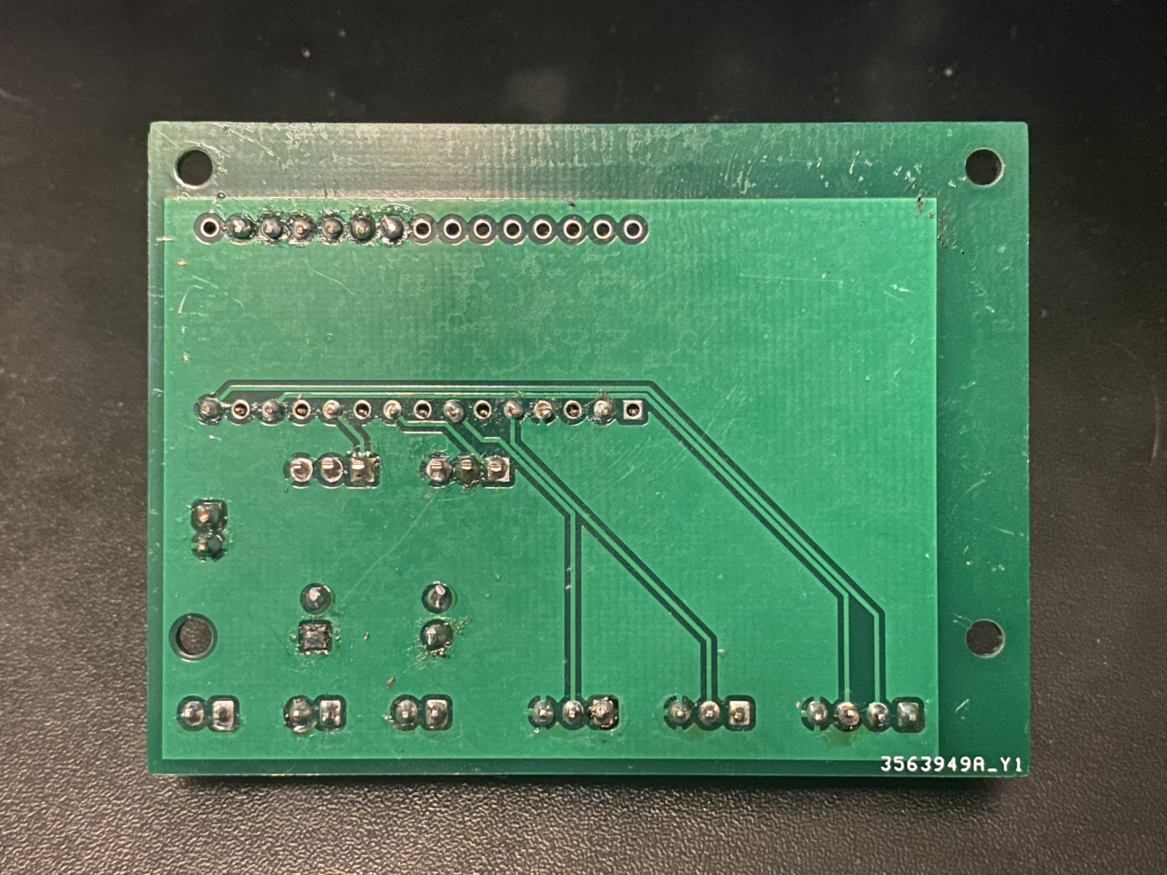
Soldering the board
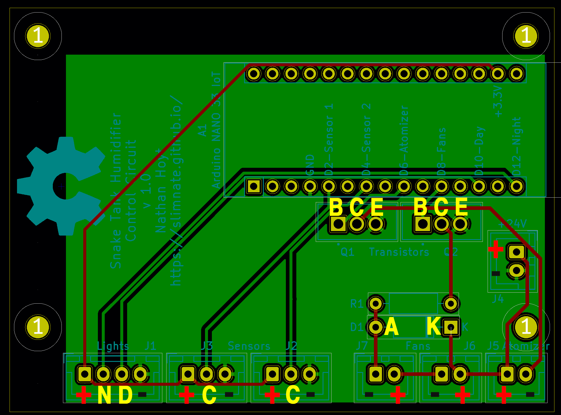
Once the circuit boards arrive, it’s time to start soldering on the various components. The annotated diagram below shows what the proper orientation is for each component.
- A1 - Arduino
- D1 - 1N4001 Diode
- J1 - 4-pin JST
- J2, J3 - 3-pin JST
- J4, J5, J6, J7 - 2-pin JST
- R1 - 10 $\Omega$ resistor
- Q1, Q2 - TIP31A power transistor
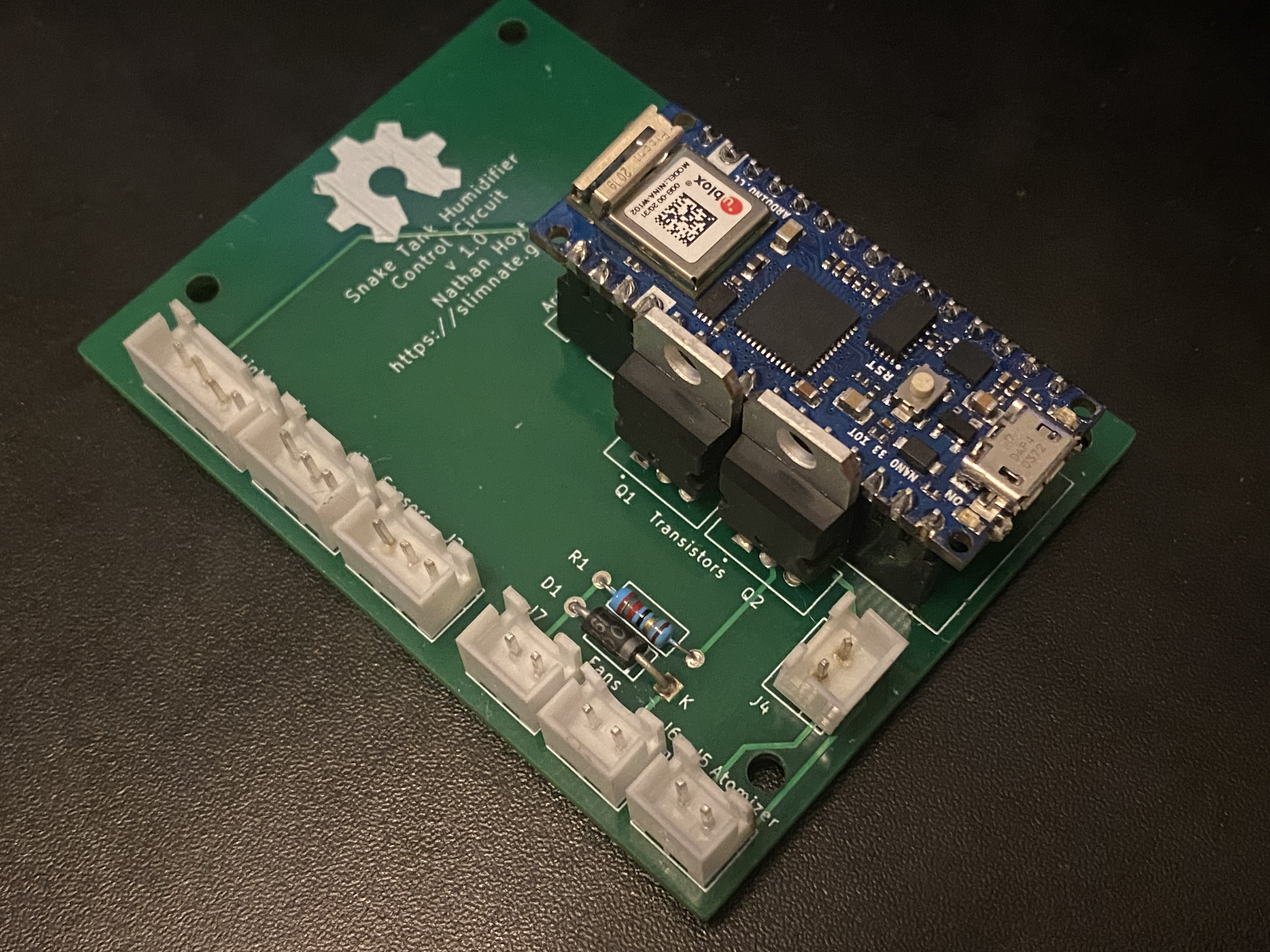
Once all the components are soldered in, this is what the completed circuit board looks like:
Assembling board in the electronics case
The final step in the electronics hardware portion of the project is to simply install the board into the 3D printed case, and install the case onto the reservoir. The circuit board simply snaps into the pegs protruding from the base, and is held in place by the posts protruding from the cover. The internal power cord also needs to be plugged in and placed in it’s slot in the circuit box as well.